|
1. What does it do ?
This module implements the design of FIR Filters by Windowing .
Two modes of design (Brick-wall type specification and Approximation type specification) are supported for Low Pass , High Pass , Band Pass and Band Elimination Type Filters. Filter Impulse Response Sequence , Frequency Response of the Filter as well as the Window Sequence , Step Response of the Filter etc are plotted with Slider Scale value read-out feature.
The designed filter impulse response and the window sequence used can be saved into *.fir file in the default project directory. The frequency response data output also can be stored in *.txt file and the plots can be saved in *.ps (Postscript Format) files in the default project directory.
2. Tab Windows

2.1 'Design Data' Window
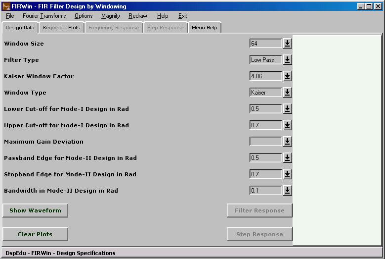
Contains pulldown boxes for selecting or entering 10 design parameters. The program allows two modes for design.
In Mode I the 'Maximum Gain Deviation Parameter' is set empty or zero. In this mode the design is carried out assuming that the specification is for a brick wall -type filter. The parameters relevant for this design will be - Window Size , Window Type , Kaiser Window Parameter (used only if Window Type is set at Kaiser Window) , Lower Cutoff Frequency in the discrete frequency domain and Upper Cutoff Frequency in the discrete domain. The Upper cutoff frequency value is ignored for Low Pass Design and Lower Cutoff Frequency is ignored for High Pass Design. Both values are used for Band Pass and Band Elimination Designs. In Mode I Design the user specifies the Window Length.
The program automatically selects Mode II Design whenever the 'Maximum Gain Deviation Parameter' is set non-zero. This parameter represents the maximum deviation from unity that is permitted in the passband and maximum deviation from zero that is permitted in the stop band. The Window Size parameter , Window Type , Kaiser Window Factor , Lower Cutoff Frequency and Upper Cutoff Frequency are ignored in this Mode II Design. In Mode II design the Window Type is set at Kaiser Window , the Window Size and Kaiser Window Parameter are calculated using the Maximum Gain Deviation Parameter specified alongwith Passband and Stopband Edge Frequencies specified. The Bandwidth Parameter is used only in Bandpass and Band Elimination Mode II Designs. In that case the product of passband edges and stop band edges are taken to be equal and the values entered in the relevant boxes are taken to be the values pertaining to the left side of frequency response with respect to center of the band.
In Mode II if 'Maximum Gain Deviation Parameter' (say Delta) is such that -20log (Delta) is less than 21, rectangular window of any length can satisfy the specs. So in such cases a rectangular window with sufficient length to satisfy the transition width spec will be taken.
In Mode II if the FIR length comes out greater than 511 it will be clamped at 511 and then the design may not satisfy the gain and transition width specifications. The calculated Window Size and Kaiser Window Parameter will appear in the corresponding boxes in the 'Design Data' window after the plots are updated once.
This Window also has a text area which displays the impulse response coefficients of the designed filter.
2.2 'Sequence Plots' Window
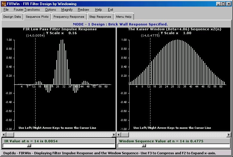
Shows the impulse response sequence of the designed filter alongwith the window sequence used as per the current parameters in the 'Design Data' window. The current Mode of Design is also highlighted. Each plot is associated with a slider scale. Clicking on the slider under the impulse response plot and moving it provides a read-out of index and impulse response coefficient at that index. Clicking on the slider under the window sequence plot and moving it provides a read-out of index and window sequence value at that index.
The plot windows have cursor lines with value display. Cursor lines can be moved by one division by Left/Right arrow keys.Pressing Ctrl-Left or Ctrl-Right moves the cursor line by larger divisions for faster traversal.

2.3 'Frequency Response' Window
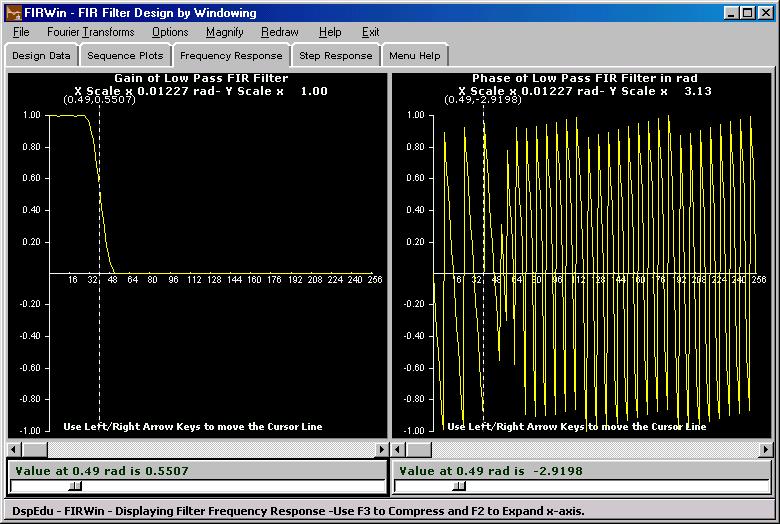
Shows the one-sided frequency response plots (when the window is raised calculates 512-point FFT and updates the plots if necessary) of the impulse response waveform currently on display in the 'Sequence Plots' window. Shows Magnitude and Angle by default. It is possible to display in Rectangular form by option change.Option change comes into effect only when a new frequency response computation is carried out.
Two slider scales appearing at the bottom of the plots allow readout of index and spectral data at that index. Magnitude spectra will have even symmetry and Angle spectra will have odd symmetry.
The plot windows have cursor lines with value display. Cursor lines can be moved by one division by Left/Right arrow keys.Pressing Ctrl-Left or Ctrl-Right moves the cursor line by larger divisions for faster traversal.

2.4 'Step Response' Window
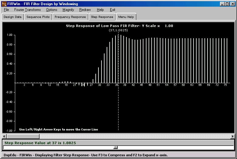
Shows the Step Response of the designed filter. The plot window comes with a slider scale which provides a read-out of step response values.

2.5 'Menu Help' Window
Raises the window and puts a brief help on the menu items in it.
3. Menubar Items
3.1 File Menu
3.1.1 Load Saved Project
Load a Sampled & Windowed Sequence and the Window Sequence used by opening a *.fir file saved in an earlier session.The default directory will be '/Projects/firfilter'
3.1.2 Save Project
Brings up a standard Windows Save Dialog box which opens into '/Projects/firfilter' by default and shows *.fir as the default extension.The number of points in the sequences and sequence data will be stored as an ascii file with selected name and 'fir' extension.The program assumes write permission in the chosen directory , overwrites with prompt and does not provide confirmation dialog.
3.1.3 Save Fourier Transform Outputs
Brings up a standard Windows Save Dialog box which opens into '/Projects/firfilter' by default and shows *.txt as the default extension. The number of points in the sequences, the sequence data , FFT output data etc.will be stored as an ascii file with selected name and 'txt' extension. The number of points calculated in FFT will be 512. The program assumes write permission in the chosen directory , overwrites with prompt and does not provide confirmation dialog.
3.1.4 Save Plots
Brings up a standard Windows Save Dialog box which opens into '/Projects/firfilter' by default and shows *.ps as the default extension.The four plots which currently appear in the four plot areas will be saved as four postscript files with selected names and 'ps' extension. The program assumes write permission in the chosen directory , overwrites with prompt and does not provide confirmation dialog.
3.2 Fourier Transforms Menu
3.2.1 Show Filter Frequency Response
Carries out 512-ponit FFT Computation for Windowed Impulse Response Sequence and plots the result in spectral plot area in two-sided version. Magnitude and Angle are plotted by default. Option to plot the real part and imaginary part is available under the Options menu.
3.2.2 Show Fourier Transform of Window
Carries out 512-ponit FFT Computation for the Window Sequence used in the filter design and plots the result in spectral plot area in two-sided version. Magnitude and Angle are plotted by default. Option to plot the real part and imaginary part is available under the Options menu.
3.3 Options
3.3.1 Fourier Transform Options
Rectangular Form - Show DFT Coefficients or Fourier Transform in Rectangular Form.
Polar Form - Show DFT Coefficients or Fourier Transform in Polar Form. This is the default.
3.3.2 Display Mode
Data Points - The plots will be line plots , a line representing the data value.
Data Envelope - A piece-wise linear curve joining the data points will be shown. Changing this option comes into effect immediately in the existing plots.
3.3.3 Numeric Result Windows Enable/Disable
Enabling will result in a window containing the convolution results popping up after every FFT computation. Default - Disable
3.3.4 Display Color Options
Normal Plot Color - The color used to draw x1(n) , x2(n) and convolution outputs.
Second Plot Color - The color used to draw a second plot in the same plot area.
Background Color - The color used as background for all the four plot areas. These three options bring up standard windows color selection dialog and changes take immediate effect
Schemes - Three color schemes in addition to default scheme are provided.Changes take immediate effect.
3.4 Magnify
Magnify the x-axis by various fixed factors. F2 key will expand the x-axis and F3 key will compress it.However this menu provides fixed scale factors for convenience.
3.5 Redraw
Re-scale all the four plot areas and redraw all the plots - needed after a resize of the main window.
3.6 Help
-This page.
3.7 Exit
4. Restrictions in the Evaluation Version
The Module can be run only 15 times and each session will last only for 10 minutes.
There are no feature limits.
5. Author
Suresh Kumar K.S
Department of Electrical Engineering
National Institute of Technology,Calicut-673601,Kerala,India
[email protected]
29th April 2004
| 


